Skills - C++, ROS, OpenCV, G2O, Motion Estimation, Bundle Adjustment
Demo
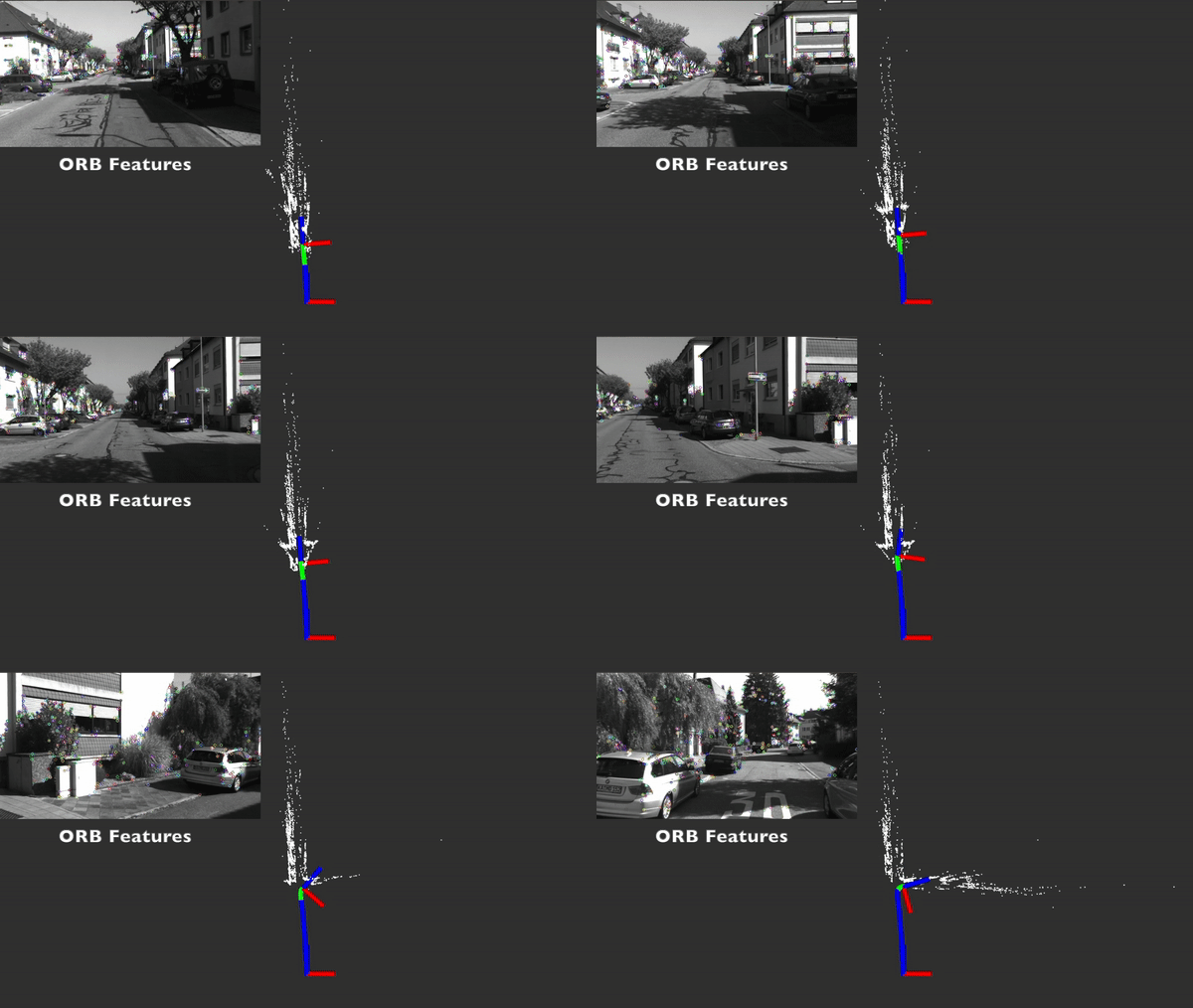
In this project, I built a stereo visual SLAM system with featured-based visual odometry and keyframe-based optimization from scratch. This video below shows the stereo visual SLAM system tested on the KITTI dataset sequence 00.
ORB Features Detected:
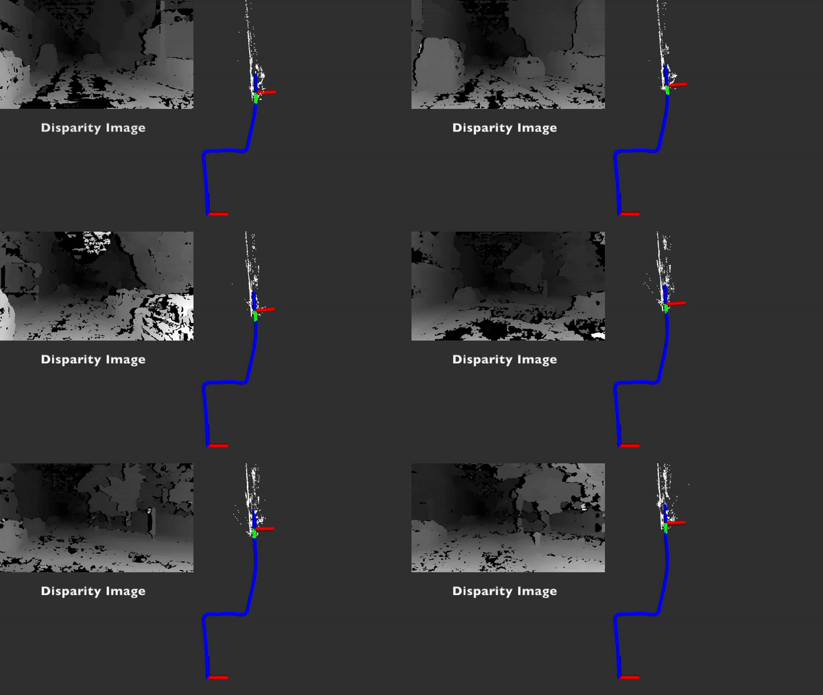
Disparity Map:
Tracking and Optimization:
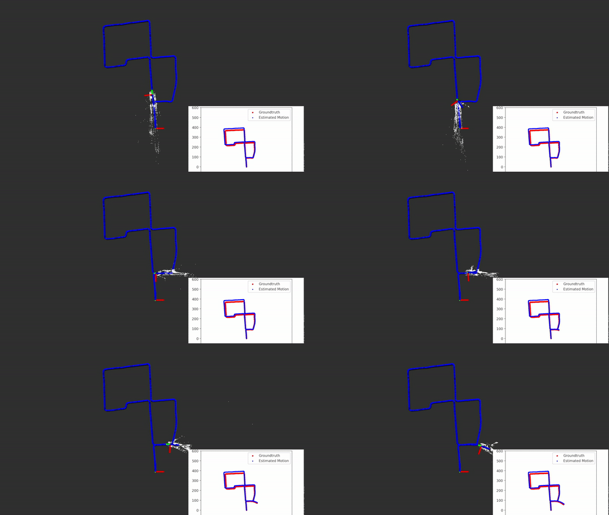
- The white point cloud shows the landmarks that are active in the map.
- Green markers show the keyframes that are undergoing optimization.
- Blue markers show the estimated trajectory.
Feature Map built:

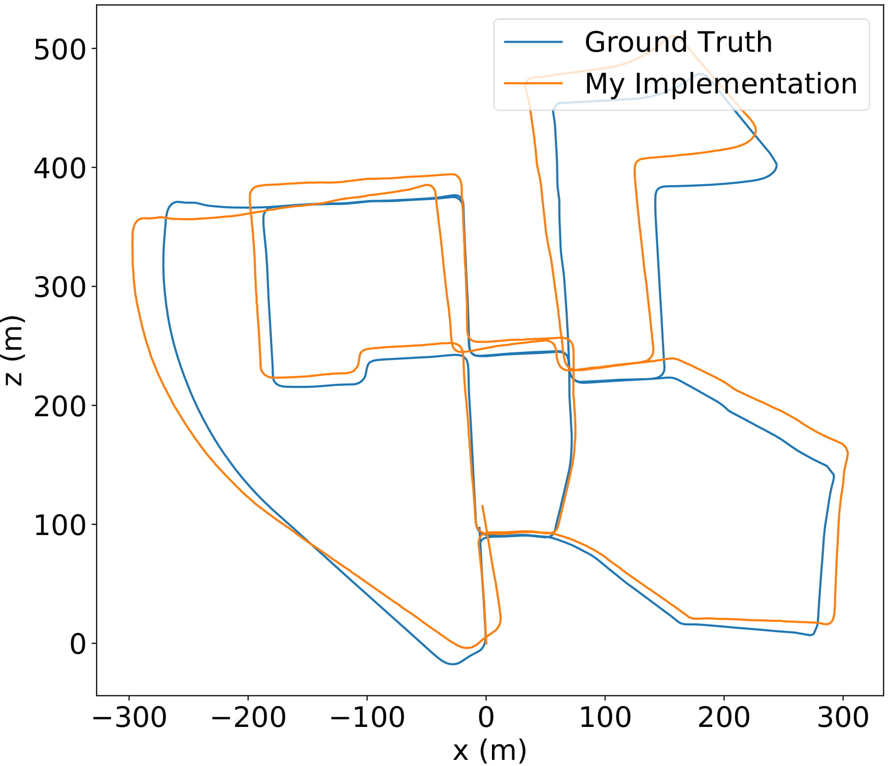
Compared to Groundtruth:

Contents
Overview
This project built a stereo visual SLAM system from scratch. It has feature-based visual odometry using ORB features, and a keyframe-based map management and optimization backend. The system is integrated with ROS.
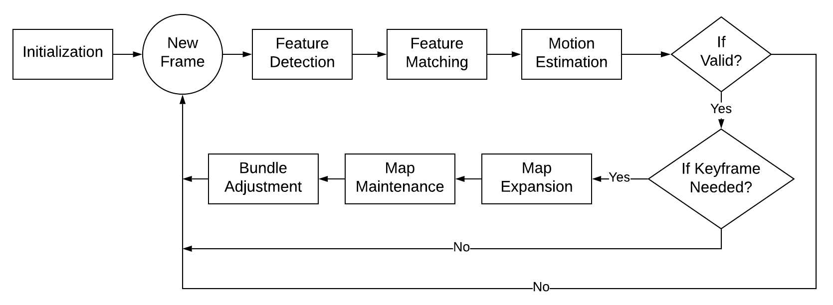
The system has six major components:
- Initialization
- Feature Detection/Matching
- Motion Estimation
- Map Management
- Bundle Adjustment
- Visualization Module
The figure below shows the flowchart of the system. Each component will be presented in detail in the Algorithms section.
This is my winter individual project at the MSR program at Northwestern Univerisity, Evanston (Jan. - Mar. 2020).
Algorithms
Initialization
In the initialization stage, depth information of detected ORB keypoints is retrieved by the stereo Semi-Global Batch Matching (SGBM) algorithm [1]. The first keyframe is created with its features attached. Landmarks are added into the map only if it is within the reliable distance (empirically ~40 times of the stereo baseline [2], 40 meters in my implementation). The connection between the features and their observations are built.
The disparity map from the SGBM algorithm:

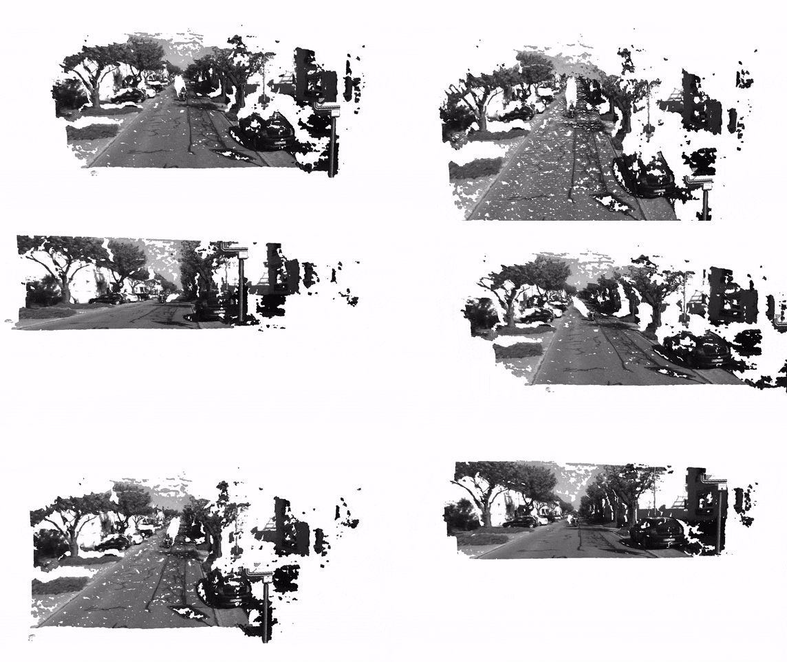
3-D Reconstruction of one frame:
Feature Detection/Matching
ORB (Oriented FAST and Rotated BRIEF) features are used in the implementation. Feature detection is completed in each frame separately, and then feature matching is implemented between adjacent frames. This avoids feature drift in long time operation [3].
The Unform distribution of features is essential to the accuracy of tracking. It can enable describing the scene with fewer features, be more robust in dynamic scenes, and reduce the drift rates. Adaptive non-maximal suppression (ANMS) algorithm was implemented to get a more uniform distribution. It only uses those features that are a maximum in a neighborhood of radius according to its corner strength. A robust coefficient was also added to require the neighbor feature has a sufficiently larger strength.
In the implementation, the suppression radius (the smallest distance to another point that is significantly stronger) for each feature is calculated. Strongest feature has a radius of infinity. The suppression radius is then ranked with 500 key points selected for each frame.
500 key points before the ANMS algorithm:

500 key points after ANMS algorithms:

The tracking accuracy also increased after implementing this algorithm:
| Seq 00 on KITTI | Translational Error (%) | Rotational Error (deg/m) |
|---|---|---|
| VO without ANMS | 4.96 | 1.84 |
| VO with ANMS | 4.55 | 1.34 |
When doing feature matching between adjacent frames, cross-check is performed to eliminate ambiguous matches. A distance threshold (30 pixels frame gap) is added to avoid no-match cases. The figure below shows a comparison of matches before and after selection:
All matches:

After cross-check and threshold selection:

Matched features are then attached to the current frame and connected to matched landmarks (3-D points in world coordinate) in the map. No 3-D points triangulation is performed for non-keyframes.
Motion Estimation
In my implementation, motion estimation is done by 3-D-2-D Perspective-n-Point (PnP) method and the random sample consensus (RANSAC) outlier rejection algorithm. I also tested the non-linear optimization method that minimizes the reprojection error using the result from PnP as an initial guess.
The result shows the pose-only optimization increases the accuracy while structure optimization (optimize both pose and landmarks) does not increase the accuracy. The optimization is implemented using the G2O framework [4]. In the final version, the single frame optimization was removed for better efficiency as it does not have a significant effect on the overall performance.
| Seq 00 on KITTI | Translational Error (%) | Rotational Error (deg/m) |
|---|---|---|
| Pose Only Optimization | 4.35 | 1.01 |
| Pose + Landmarks Optimization | 4.64 | 1.12 |
The motion estimation pipeline is a state machine with three states. When ten consecutive frames are rejected, the state will be set to lost. A frame will be rejected if the estimated motion is too large, or the number of inliers is not enough.

Map Management
A frame is selected as a keyframe when the following requirements are met:
- Number of inliers less than 80
- This means a new keyframe is needed.
- Experienced a large rotation
- My tests show adding more keyframes when rotating can increase performance.
- Motion estimation is valid
- The quality of this frame is good.
When a new keyframe is selected, new features points in this frame are then triangulated. Landmarks within reliable depth are added to the map. Observations and connections between features and landmarks are also added.
The number of active keyframes is kept to be ten in the map to reduce the computation. Additional keyframes will be removed from the optimization. The closest keyframe will be deleted if its distance to the current camera position is smaller than 0.2. Otherwise, the farthest frame is removed. This can avoid keyframes concentrating at the same location when the robot is not moving. Concentrated keyframes can have a harmful effect on bundle adjustment. Observations are also removed along with the keyframe.
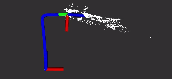
Green markers show keyframes that are currently active and undergoing optimization:
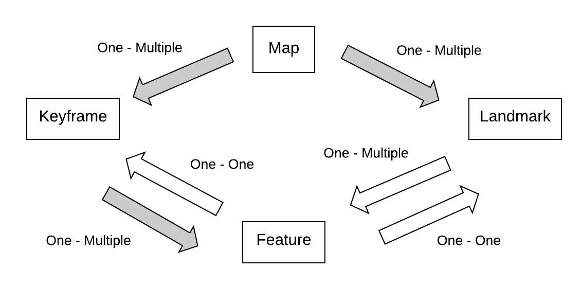
This is the data structure used in my implementation. A map owns multiple keyframes and landmarks. A keyframe owns multiple features. A feature knows the ID of its frame, and the connection between features and landmarks are also established. Keyframes and landmarks are stored in a hashtable (unordered_map in C++) to ensure O(1) time complexity. Gray arrows in the figure denotes the ownership.
Bundle Adjustment
Bundle adjustment is performed on active keyframes and landmarks. The figure below illustrates the keyframe-based bundle adjustment ( denotes camera poses, and denotes landmarks). Compared to filter-based methods, where previous poses are removed from the map and summarized into a probability distribution at the current time, keyframe-based methods control the computational scale by selecting a subset of all the frames as keyframes [5].

G2O framework is used in the implementation. Pose-only optimization only modifies the camera poses to reduce the reprojection error, while structure optimization modifies both the poses and landmarks positions. Levenberg–Marquardt method is used for optimization. The cost function is:
The computational cost is reduced by utilizing the sparsity of the H matrix. The map management module in my implementation forms a sliding window, which maintains its sparsity.
In the final version, ten iterations are performed to reject outliers. Ten iterations of structure optimization are then completed to optimize both landmarks and poses. Another ten iterations of pose only optimization is also performed.
A landmark is considered as an outlier if its cost is larger than a threshold. The threshold will be increased if half of the landmarks are regarded as outliers in the first few iterations. Although only landmarks with reliable depth information are added for optimization, the threshold for ‘reliable depth’ is mostly an empirical result. It turns out that the performance of optimization is sensitive to the threshold. A smaller threshold shows a significantly better performance. This indicates that triangulated landmarks that are far away from the camera are not accurate. It makes sense as the stereo system can degenerate into a monocular one if the object is far away from the camera. Therefore, to maintain the robustness of the system, optimized landmark positions are not updated into the map.
Although the tracking thread and the optimization thread can be run in parallel according to state-of-art keyframe-based SLAM systems [6], they are completed in sequence for simplicity in the implementation.
Results
The table below shows the performance of my implementation on KITTI Dataset sequence 00 [7]. The runtime is around 0.18s for a keyframe and 0.04s for a non-keyframe.
| Seq 00 on KITTI | Translational Error (%) | Rotational Error (deg/m) |
|---|---|---|
| Without Optimization | 4.40 | 1.38 |
| With Optimization | 4.17 | 1.37 |
The figure below shows the trajectory estimated by my implementation compared to the ground truth. The system has been tested on KITTI sequence 00 (urban environment) and 01 (highway) without lost.
Future Work
- A loop closure module can be added to ensure the global consistency of the map
- An occupancy grid map can be built by detecting drivable areas. This can be completed by techniques including plane detection, lane line detection, semantic segmentation, etc.
References
[1] H. Hirschmuller, “Stereo Processing by Semiglobal Matching and Mutual Information,” in IEEE Transactions on Pattern Analysis and Machine Intelligence, vol. 30, no. 2, pp. 328-341, Feb. 2008.
[2] Mur-Artal, Raul, and Juan D Tardos. “ORB-SLAM2: An Open-Source SLAM System for Monocular, Stereo, and RGB-D Cameras.” IEEE Transactions on Robotics 33, no. 5 (2017): 1255–1262.
[3] Nister, D, O Naroditsky, and J Bergen. “Visual Odometry.” In Proceedings of the 2004 IEEE Computer Society Conference on Computer Vision and Pattern Recognition, 2004. CVPR 2004, 1:I–I. IEEE, 2004.
[4] R. Kümmerle, G. Grisetti, H. Strasdat, K. Konolige and W. Burgard, “G2o: A general framework for graph optimization,” 2011 IEEE International Conference on Robotics and Automation, Shanghai, 2011, pp. 3607-3613.
[5] Strasdat, Hauke, J.M.M. Montiel, and Andrew J. Davison. “Visual SLAM: Why Filter?” Image and Vision Computing 30, no. 2 (February 1, 2012): 65–77.
[6] Klein, G, and D Murray. “Parallel Tracking and Mapping for Small AR Workspaces.” In 2007 6th IEEE and ACM International Symposium on Mixed and Augmented Reality, 225–234. IEEE, 2007.
[7] Geiger, Andreas, Philip Lenz, and Raquel Urtasun. “Are We Ready for Autonomous Driving? The KITTI Vision Benchmark Suite.” In Conference on Computer Vision and Pattern Recognition (CVPR), 2012.