Skills - SolidWorks, 3D Modeling, Mechanical Design, FEA, Failure Prediction, 2D Drawing, Component Selection, Material Selection
Project Overview:
This project designed a freight elevator (dumbwaiter), including the car, housing, support frames, and transmission connections.
Finite element analysis, design analysis, and components selection were also conducted.
The specifications are as follow:
- Maximum Car Speed: 0.6 m/s
- Rated Load: 12 kg
- Usable Car Space: 240 x 300 x 500 mm (Width x Depth x Height)
- Shaft Space: 380 x 490 mm (Width x Depth)
Mechanical Design:
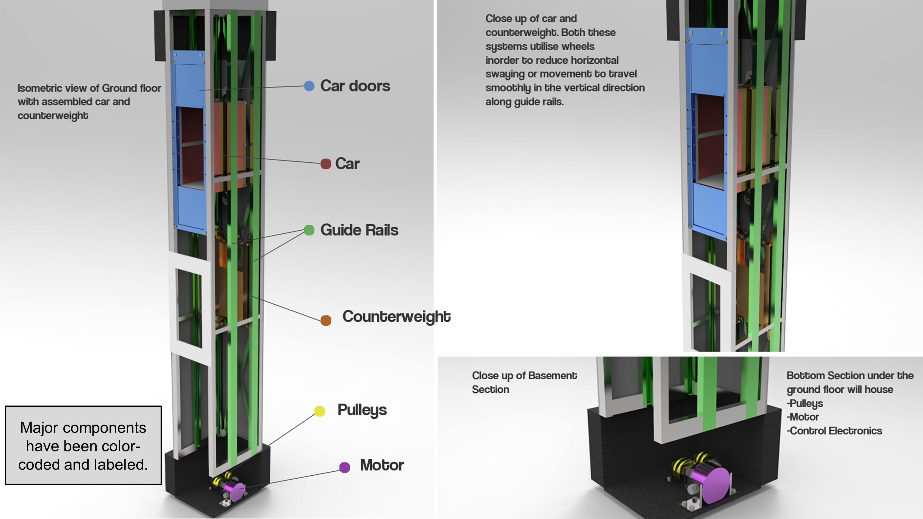
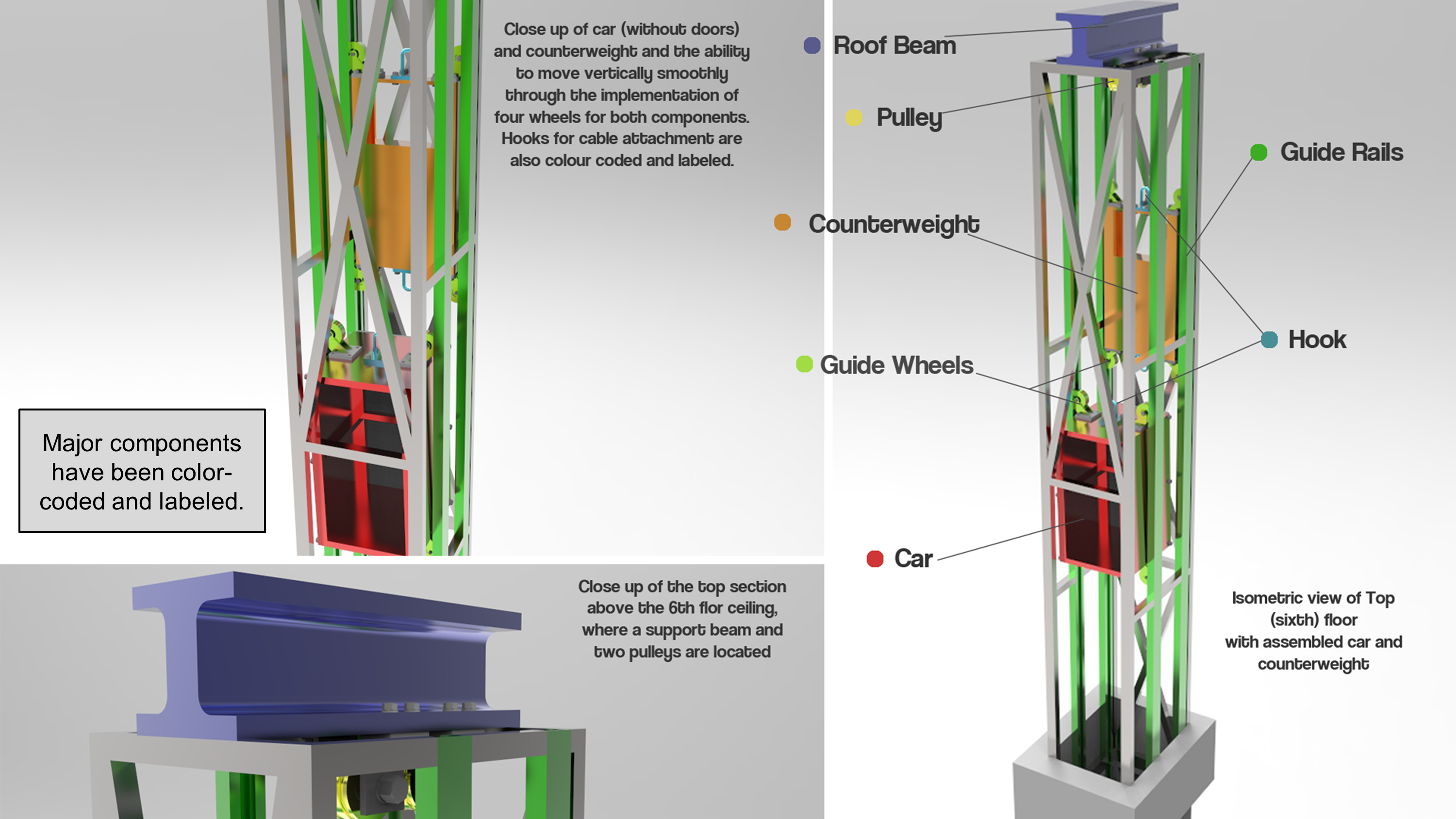
The purpose of this design was to create a dumbwaiter system that would be able to transport goods through a six-story hospital effectively. This dumbwaiter uses a cart and counterweight system, where the cart and counterweight are interconnected through pulleys. Therefore, the cart and counterweight move inversely with respect to each other. By utilizing this design feature, the pulley system is in constant tension, and hence the motor will exert a reduced maximum force for the respective movement of the car during operation. Guide rails are used to stabilize the car and counterweight during motion and restrict any horizontal movement.
The mechanical design parts include:
- Cart
- Cable
- Pulley system
- Shaft and brackets
- Bearings
- Structure
- Braking system
- Doors
- Selection of screws and bolts
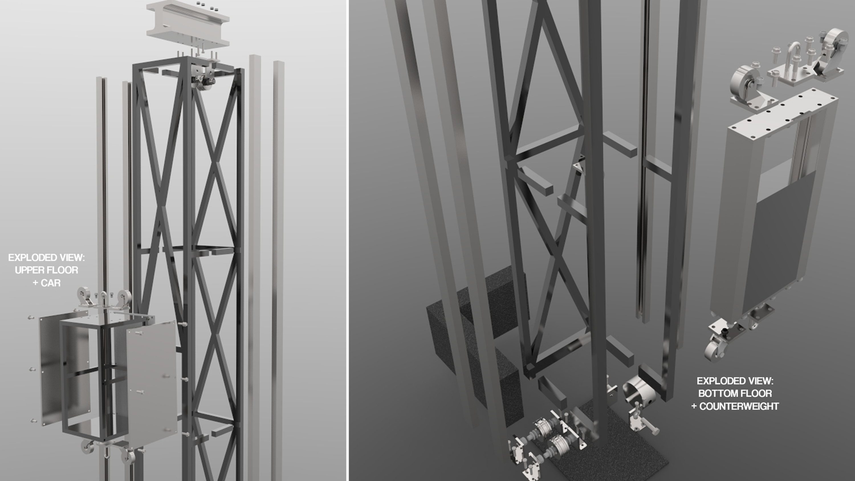
The initial conceptual design is shown below:
While fulfilling the primary objective of creating a system that can successfully and effectively transport goods between levels, various design aspects are also considered, including cost, weight, ease of manufacturing.
Alongside the car and internal structure, all mechanical requirements for the dumbwaiter system to function have been considered and either designed or selected based on existing purchasable parts. Further safety implementations and features such as internal/external doors and safety stopping mechanisms have been detailed in the design. While costing and manufacturing methods have also been explored to validate this design as a viable, safe, and operational system.
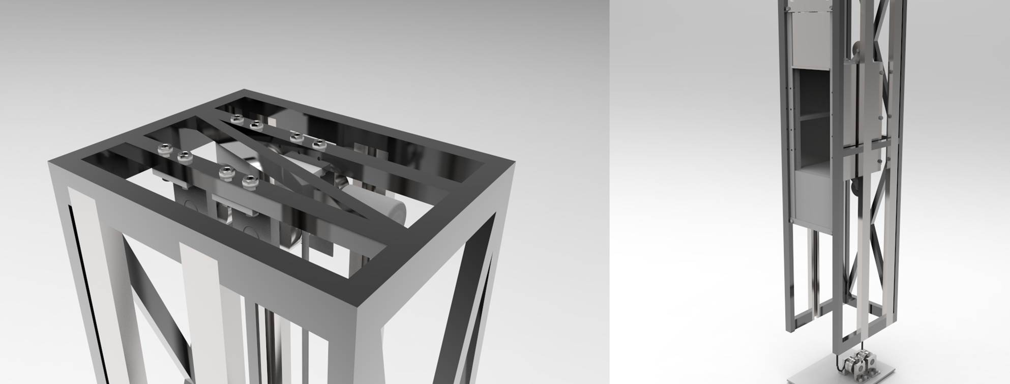
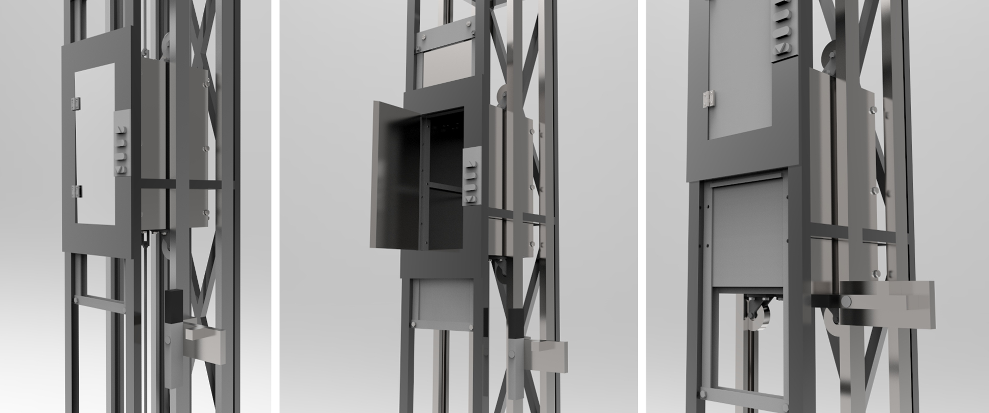
The final design is shown below:
Design Analysis:
To analyze the reliability and strength of the design under loading and forces present when in operation, hand calculations, and finite element analysis (FEA) has been undertaken on all major components to avoid failure. Various iterations have then been undertaken to obtain reasonable safety factors. Through this iterative process, design changes and material changes have been considered before the presentation of the final design.
Optimization and Finite Element Analysis:
In the process of moving from the initial concept to final, an optimization process has been undertaken to detail the relevant changes from the initial design to the final design. These changes range from the positioning of components, material changes, dimension changes, and design changes.
Acknowledgment:
This project was the teamwork of group-19 (MEC3416, Semester 2, 2017) at Monash University.